

When Rebuilding a Rear Differential Proper Gear Mesh Pattern UPDATED
When Rebuilding a Rear Differential Proper Gear Mesh Pattern
Gear tooth patterns are harbingers… they can foretell whether your ring and pinion gear set is going to live a long and prosperous life or if it'southward doomed to an impending catastrophic failure. Pulling off a proper differential setup comes down to precise adjustments. Parameters like pinion depth, backlash, pinion-bearing preload, and carrier-bearing preload allow you to fine tune the human relationship between gear teeth to ensure proper meshing and ultimate durability.
Checking the Pattern
Nosotros can determine how gears mesh past changing how close the pinion gear is to the band gear centerline. While we can't physically see how the gears really relate to each other, we can coat their mating surfaces with gear-marking compound and read the patterns the gears create as they mesh. Genuine gear-marking compound offers a clear indication of gear contact without running or smearing. Anything other than gear marking compound (such as blue machinist dye) will non give a articulate indication of molar contact. Dilute the marking chemical compound with a small corporeality of oil if necessary to create a smooth, merely not runny, paste. Glaze three or iv ring-gear teeth in at to the lowest degree two places with a moderate amount of chemical compound and rotate the ring gear around the pinion gear four or five times in both directions. Rotate by grabbing and turning the ring gear, not the pinion. Pinion resistance against the rotating ring gear helps establish a skilful blueprint. Pinion bearing preload usually provides enough resistance for a good pattern, but boosted resistance tin be added by wrapping a shop towel around the yoke and pulling the two ends tight.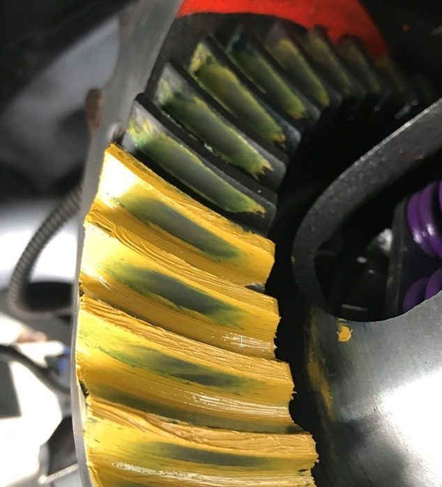
An alternative method for checking gear patterns in cases where reading the pattern is hard involves spinning the pinion. Paint iii or 4 ring gear teeth as usual on both coast and drive sides of the teeth. Using a ½" drive adapter on a manus drill (not on an impact gun/driver) spin the pinion for xxx to threescore seconds in each direction while applying elevate to the edge of the band gear. Not only does this typically produce a articulate, well defined pattern on the painted teeth, only it creates a negative or "ghost" blueprint on the non-painted teeth that may provide additional insight to the pattern, while likewise conveniently showing any potential run out issues (where the pattern is shifting from heel to toe as the gear is rotated). This technique as well helps to minimize diagonal striping in the blueprint that occurs when rocking the gears back and forth, which can pb to misdiagnosed patterns. The downwardly side of this method is more cleanup betwixt adjustments to remove the compound but the additional data is well worth the attempt.
Here is a good example of the alternate technique. Yous can encounter on the bottom couple of teeth that were painted how the compound got smeared resulting in diagonal striping, and hard to read, as opposed to the "ghost" or negative patterns on the not-painted teeth being quite clear and well defined.
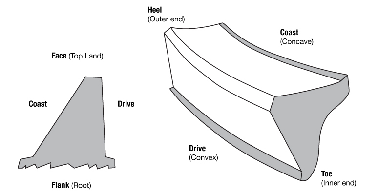
Anatomy Of A Gear Tooth
The pattern'south position to the tooth face (ridge/top country) and flank (valley/root) indicates pinion depth. Disregard the design'southward position to the tooth's heel (band gear outside bore) or toe (band gear inside diameter). Gear patterns change from heel to toe, but in almost cases an ideal heel-to-toe design is impossible to achieve. Furthermore, the housing itself influences the heel-to-toe pattern and the pattern cannot exist changed without machine work. Trying to obtain a pattern centered exactly between the heel and toe usually leads to frustration and a noisy gear set if the face to flank pattern is non correct. Instead, concentrate only on the position of the pattern and how it relates from face to flank of the ring gear teeth.
Cause, Effect, Action
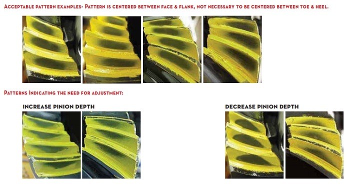
A contact pattern centered from confront to flank indicates the correct pinion depth.
A contact pattern closer to the gear face up means the pinion is as well far abroad from the ring gear. To correct the pattern, move the pinion toward the ring gear centerline.
A contact pattern closer to the gear flank means the pinion is too close to the ring gear. To correct the pattern, move the pinion away from the ring gear centerline.
How To Maneuver Your Pinion Pattern
1. Apply shims to move the ring gear closer to the pinion gear to decrease backlash.
2. Utilise shims to move the band gear farther from the pinion gear to increase backlash.
3. Use shims to movement the pinion closer to the ring gear to move the drive pattern deeper on the tooth (flank contact) and slightly toward the toe. The coast pattern will move deeper on the tooth and slightly toward the heel.
4. Use shims to motion the pinion further away from the ring gear to motion the bulldoze design toward the top of the molar (face) and slightly toward the heel. The coast design will move toward the meridian of the tooth and slightly toward the toe.
Make Large Pinion Depth Adjustments First
When changing the pinion depth, make big changes until the pattern is shut to ideal. Consider 0.005" to 0.015" a big alter and 0.002" to 0.004" a small change. Intentionally, make adjustments that movement the pinion too far at first. If the pinion moves too far and the pattern changes from one extreme to the other, the correct pattern lies somewhere between the 2 adjustments. In one case you get close to the correct pinion depth, make smaller changes until the design centers between the face and the flank of the ring gear teeth. In one case the backlash and pinion depth run across tolerances, remove the carrier and establish the final pinion begetting preload.
Properly setting your ring and pinion gear is an important function of the drivetrain experience. Getting it right is the divergence between decades of like shooting fish in a barrel miles and a flurry of headaches and chunked-out gears later only a few miles.
Shop Re-Gear Kits
DOWNLOAD HERE
When Rebuilding a Rear Differential Proper Gear Mesh Pattern UPDATED
Posted by: samuelporm1978.blogspot.com

Comments
Post a Comment